Calibration of protection relays is critical to the reliability and safety of electrical power systems. This guide is designed to inform engineers, power system operators, and technical enthusiasts about the calibration process, its importance for different relay types, and best practices based on engineering principles and industry standards.
As an independent professional in the electrical power field, my aim is to simplify these concepts and provide helpful resources for those working with or studying protective relays.
Protection Relays: Types and Calibration Needs
Protection relays are categorized into:
Electromechanical Relays:
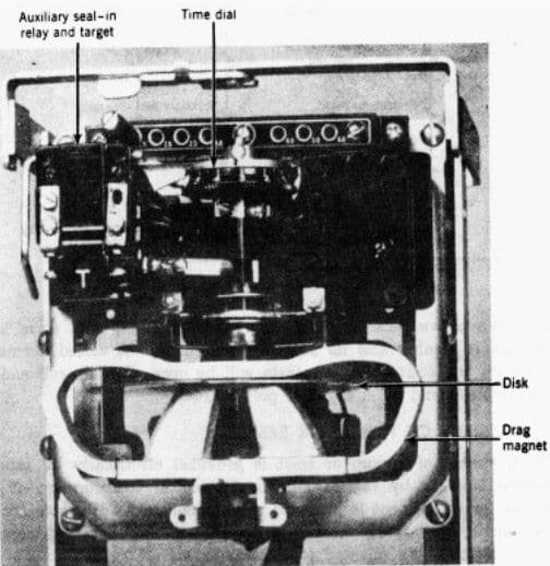
- Operate using mechanical principles like induction and magnetism.
- Require periodic calibration due to wear, environmental effects, and mechanical drift.
Numerical Relays:
- Use microprocessors to analyze and process signals.
- Calibration focuses on verifying external components (e.g., CTs/PTs) and ensuring software-driven thresholds are correct.
Key Calibration Needs
For Electromechanical Relays:, calibration adjusts physical components. For numerical relays, it ensures accurate signal interpretation and alignment with system conditions.
Steps in Calibrating Protection Relays
1. Understanding Relay Settings
Relay settings define operational thresholds:
- Pickup Current (): The current level where tripping occurs.
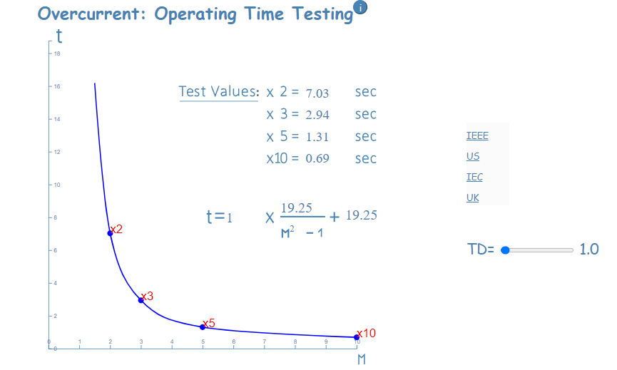
- Time-Current Characteristic:
, where:- = operating time,
- = time multiplier constant,
- = fault current,
- = pickup current,
- = characteristic curve exponent.
Settings are derived from coordination studies to ensure selective operation.
Get access to testing values: Overcurrent: Operating Time Testing
2. Testing and Adjustment
- For electromechanical relays:
- Adjust mechanical components to match desired trip points.
- For numerical relays:
- Validate analog-to-digital conversion (ADC) accuracy and firmware-defined thresholds.
3. Validation
- Inject test signals (e.g., for a relay) and verify proper operation.
- Document results to confirm compliance with standards.
Practical Engineering Concepts
CT/PT Accuracy
Relay performance depends on accurate sensing by CTs/PTs. Common parameters include:
- Ratio Error:
- Phase Angle Error: Affects phasor calculations critical for protection logic.
Impedance Protection
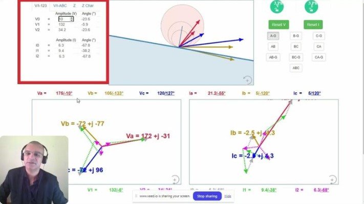
Impedance relays use the relationship:
to detect faults in specific zones. Calibration ensures accurate fault zone detection and selectivity.
Watch my video on distance relay:
Industry Standards
Relay calibration aligns with:
- IEEE C37 Series: For testing and performance of relays.
- IEC 61850: For communication and data handling in protective relays.
These standards specify tolerances, such as for voltage measurements and for current thresholds.
FAQs
Q1: Do numerical relays require calibration?
Numerical relays usually need validation of input signals (CT/PT accuracy) and firmware settings rather than traditional calibration.
Q2: What is the main cause of drift in electromechanical relays?
Mechanical wear, environmental factors (temperature, dust), and aging components can cause drift in performance.
Q3: What are the most common calibration tools?
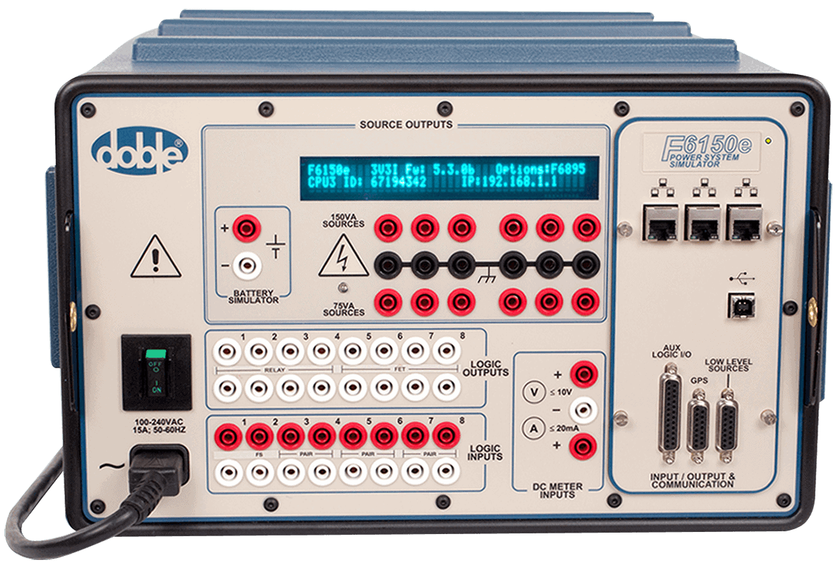
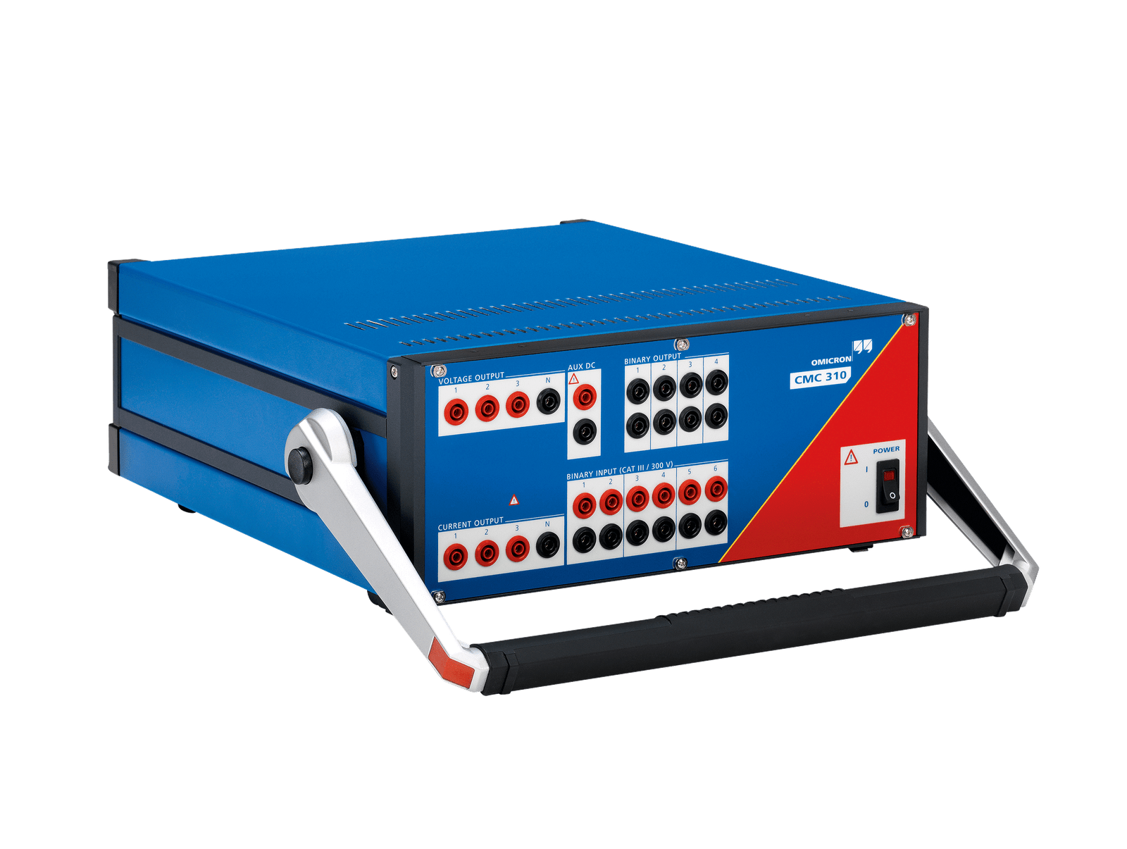
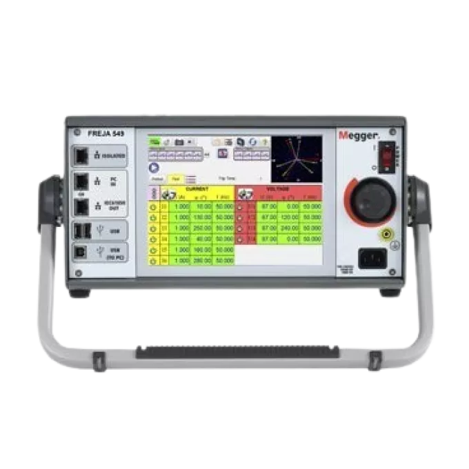
Calibrated voltage/current sources and test sets like Doble F6150, Omicron CMC, or Megger SMRT are widely used.
Conclusion
Calibration of protection relays ensures reliable performance and safety in power systems. While electromechanical relays demand periodic calibration, numerical relays focus on validation and firmware integrity. Adhering to industry standards minimizes risks and improves system reliability.
Explore tools and resources for calibration from leading manufacturers like Doble, Omicron, and Megger.

