As engineers, we’ve all encountered the challenges of overcurrent relay coordination. Fine-tuning settings to achieve precise coordination can be time-consuming and prone to error. To address these pain points, I developed a custom tool that simplifies coordination studies for a typical step-down transformers.
This tool is tailored for a typical step-down transformer with default 40MVA, 32 kV/11 kV voltage ratings. It offers features like drag-and-drop relay curves, multiple standard compatibility, and intuitive fault analysis—all designed to make your work more efficient and accurate.
Key Features of My Tool
1. Dynamic Curve Customization
One of the standout features is the ability to drag-and-drop relay curves directly within the tool. This enables engineers to:
- Adjust pickup values and time dials effortlessly.
- Customize settings for high-voltage (HV) and low-voltage (LV) sides.
- Avoid overlapping coordination zones through visual clarity.
2. Support for Multiple Standards
The tool supports global protection standards, ensuring its versatility for diverse projects. Options include:
- IEC Standards
- IEEE Curves (Inverse and Extremely Inverse)
- UK, US and SEL
Switching between these standards is as simple as selecting from a dropdown menu.
3. Fault Analysis Made Simple
Understanding fault behavior is critical for proper relay coordination. The tool calculates:
- HV and LV fault currents for accurate relay settings.
- Trip times for HV and LV relays to ensure proper sequencing.
- Coordination gaps, preventing overlaps and minimizing misoperations.
4. Educational and Practical Application
This tool is not just for professionals, it’s also a great resource for students and trainees. With its clear visualization of relay curves and fault analysis, it serves as an excellent teaching aid for understanding overcurrent protection concepts.
Practical Example: A 400 MVA Transformer Study
Let’s walk through a practical use case for this tool:
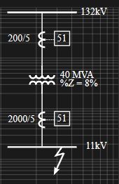
Transformer Specifications:
- Size: 400 MVA
- Voltage Ratings: 32 kV (HV) / 11 kV (LV)
- Impedance: 8%
- CT Ratios: 200:1 (HV), 2000:1 (LV)
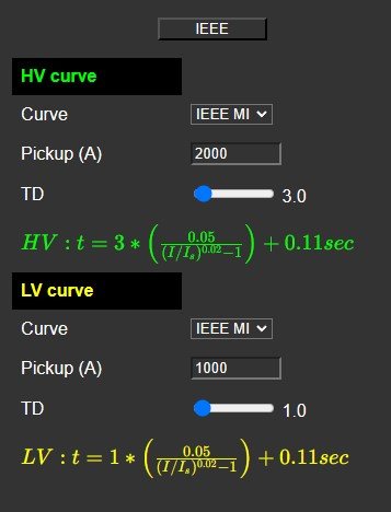
Relay Settings:
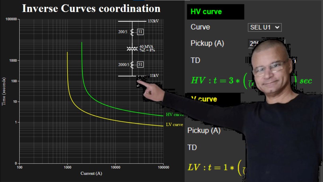
- HV Side: Moderately Inverse Curve, Time Dial = 3
- LV Side: Moderately Inverse Curve, Time Dial = 1
- Results:
- The HV relay trips in 0.8 seconds during faults, while the LV relay trips in 0.6 seconds, maintaining a 200 ms coordination gap.
- Adjustments can be made directly within the tool, ensuring precise alignment with system parameters.
My Vision for This Tool
This tool is more than a product, it’s a culmination of my hands-on experience in relay coordination and my desire to simplify the process for other engineers. I built it to bridge the gap between complex theory and practical application, offering a user-friendly interface that enhances accuracy and understanding.
What’s Next?
This is just the beginning. I’m committed to expanding the tool’s features, incorporating user feedback, and making it even more versatile.
Your feedback is invaluable in shaping the future of this tool. Let’s collaborate to refine and improve the way we approach overcurrent protection.
By engineers, for engineers, this tool represents my dedication to simplifying relay coordination while maintaining the precision required for effective transformer protection.
Get access to the tool here: link