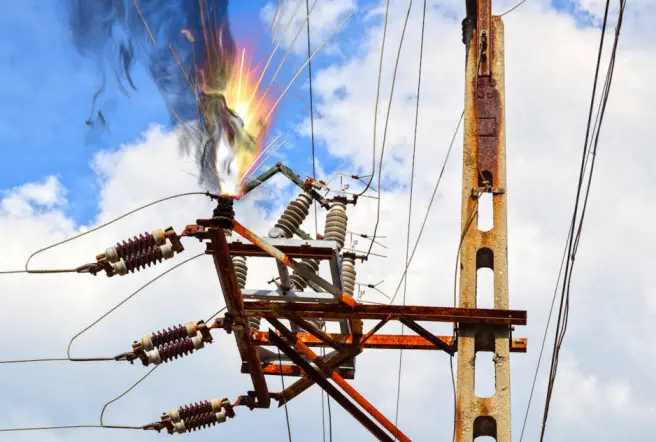
Power system protection is a critical aspect of electrical power network transmission and distribution. Its primary goal is to ensure the safe and reliable operation of the power system by detecting and isolating faults or abnormal conditions.

These can include short circuits, ground faults, and other disturbances. Below, we will explore the core concepts and principles of power system protection, along with examples to illustrate their applications.
Objectives of Power System Protection
The main objectives of power system protection are:
- Minimize Equipment Damage: Limit the damage caused by faults to critical infrastructure.
- Maintain System Stability: Isolate faults to prevent system-wide disturbances.
- Enhance Safety: Ensure safety for personnel and infrastructure by mitigating dangerous conditions.
To achieve these goals, protection systems must identify faults rapidly and accurately, isolating the faulted section while leaving unaffected areas operational. This minimizes service disruptions and maintains stability in the power network.
Key Components: Relays and Circuit Breakers
Relay protection forms the backbone of power system protection. A relay monitors electrical quantities—like current, voltage, or impedance—and triggers action if abnormal conditions are detected. When a fault is detected, the relay sends a trip signal to circuit breakers, instructing them to open and disconnect the faulted section.
Example: Consider a high-voltage transmission line with a fault current exceeding normal operating limits.

The overcurrent relay detects this condition and sends a trip signal to the circuit breaker, disconnecting the line in milliseconds to prevent equipment damage and maintain stability.
List of Power System Protection with ANSI/IEEE Codes
Generator Major Protections
- Thermal / Unbalance / Over / Under Current - 49 (Thermal Relay), 46 (Reverse Phase or Phase-Balance Current), 50/51 (Instantaneous/Time Overcurrent)
- Pole Slip - 78 (Out-of-Step Protection)
- Field Failure - 40 (Loss of Field)
- Over / Under Voltage - 27 (Undervoltage), 59 (Overvoltage)
- Over / Under Frequency - 81 (Frequency Relay)
- Earth Fault / Restricted Earth Fault (EF) / 100% Earth Fault - 64 (Ground Fault)
- Rotor Earth Fault - 64R (Rotor Earth Fault)
- Differential Protection - 87 (Differential Protection)
- Forward / Reverse Power Protection - 32 (Power Directional Relay)
Busbar Major Protections
- Differential Protection - 87 (Differential Protection)
Transformer Major Protections
- Overcurrent - 50/51 (Instantaneous/Time Overcurrent)
- Earth Fault - 50N/51N (Neutral Overcurrent)
- Restricted Earth Fault - 64REF (Restricted Earth Fault Protection)
- Standby (or) Sensitive Earth Fault - 51G (Ground Time Overcurrent)
- Differential Protection - 87T (Transformer Differential Protection)
- 2nd Harmonics Blocking - 87 (Differential with Harmonic Restraint)
- Over Fluxing - 24 (Overfluxing Protection)
- Mechanical Protection (Buchholz, WTI, OTI, PRV) - 63 (Pressure Relay), 26 (Temperature Monitor)
Transmission Line Major Protections
- Overcurrent / Earth Fault - 50/51 (Instantaneous/Time Overcurrent), 50N/51N (Neutral Overcurrent)
- Over / Under Voltage - 27 (Undervoltage), 59 (Overvoltage)
- Directional Earth Fault - 67N (Directional Earth Fault)
- Distance Protection (Schemes, SOTF, Power Swing) - 21 (Distance Relay)
- Differential Protection - 87L (Line Differential Protection)
- Auto Reclose Function - 79 (Reclosing Relay)
Motor Feeder Major Protections
- Overcurrent / Earth Fault - 50/51 (Instantaneous/Time Overcurrent), 50N/51N (Neutral Overcurrent)
- Over / Under Voltage - 27 (Undervoltage), 59 (Overvoltage)
- Motor Startup - 14 (Underspeed), 66 (Not Permitted Time Delay)
- Jam / Stall Protection - 51LR (Locked Rotor Overcurrent)
- Unbalance - 46 (Phase-Balance Current Relay)
- Thermal Overcurrent - 49 (Thermal Relay)
- Circuit Breaker Failure - 50BF (Breaker Failure)
Common Protection Schemes
Different protection schemes are used depending on the equipment and conditions. Below are key protection schemes with relevant examples:
1. Overcurrent Protection (ANSI 50/51)
Overcurrent protection is triggered when the measured current exceeds a preset threshold. It is commonly used for feeder protection.
- Application: Protecting a 138 kV transmission line where a fault current exceeds the line’s rated current. The overcurrent relay, set with a pickup current just above normal load, detects the fault and sends a signal to the breaker to trip.
IEEE/IEC Standards: This aligns with IEEE C37.112 standards for time-overcurrent relay settings and performance.
2. Differential Protection (ANSI 87)
Differential protection compares currents entering and leaving a protected zone. A fault within this zone triggers a trip due to the imbalance in current.
- Application: In a transformer differential protection scenario, currents are measured on both primary and secondary sides. A fault inside the transformer (e.g., a winding fault) leads to a difference in current between the sides, activating the differential relay to isolate the transformer.
IEEE/IEC Standards: Referenced by IEEE C37.91 for differential protection of transformers.
3. Distance Protection (ANSI 21)
Distance relays calculate impedance (voltage to current ratio) along a transmission line. A drop in impedance indicates a fault closer to the relay location.
- Application: For a 220 kV transmission line, if a fault occurs 30% along the line length, the relay compares the measured impedance with pre-set zones. If the fault falls within Zone 1 (typically 80-90% of the line), it initiates an immediate trip.
IEEE/IEC Standards: Distance relays adhere to IEEE C37.113 standards for their design and application.
4. Transformer Protection
Transformers are crucial in power systems, necessitating specialized protection schemes like differential, overcurrent, and temperature monitoring.
- Application: A 400 MVA transformer utilizes differential protection to detect internal faults. Additional overcurrent relays are installed for backup, and temperature sensors trigger alarms for overheating conditions.
IEEE/IEC Standards: Relevant guidelines include IEEE C57.12.00.
Relay Settings and Fault Analysis
To ensure effective protection, relay settings must be carefully calculated. Settings involve defining thresholds—like pickup currents or impedance limits—based on the power system’s characteristics. Short-circuit studies and coordination studies are critical to setting these parameters. For instance, proper time coordination between upstream and downstream relays prevents unnecessary tripping, allowing selective isolation of faults.
Example: For a 110 kV line with a typical fault current of 5 kA, the relay’s pickup setting might be set to 1.2 times the maximum load current, with a time dial setting that coordinates with downstream relays.
Fault Analysis is another critical element, involving accurate calculations of fault currents, fault locations, and clearing times. Techniques like symmetrical components analysis and impedance-based methods help determine the magnitude and location of faults to ensure proper relay operation.
Conclusion
Power system protection is an essential aspect of electrical power network transmission and distribution, focused on detecting and isolating faults with precision. By employing relay protection schemes, fault analysis, and carefully calculated settings, the protection system ensures the reliability and safety of the network. Proper configuration of these elements is vital to minimizing disruptions and maintaining stable power system operations.
Essence: Effective power system protection relies on quick and accurate fault detection using various relay schemes, ensuring safety and continuity in high-voltage power networks.
For further detailed guidance, consider consulting IEEE C37.2 for standard device function numbers.