Accurately detecting and protecting against single-phase-to-ground faults is one of the most challenging tasks in distance relay protection. At the heart of this challenge lies the K factor, a parameter integral to ensuring accurate relay operation and fault identification. In this blog, we will explore its significance, practical challenges, and how different schemes address fault detection and relay logic.
What Is the K Factor?
The K factor (or zero-sequence compensation factor) adjusts the measured impedance for the phase-to-ground fault loop by accounting for the contribution of zero-sequence currents. This compensation is critical because zero-sequence current introduces an offset in the fault impedance. Without proper compensation, the relay risks misoperation, particularly for single-phase-to-ground faults.
Mathematically, the K factor is expressed as:
Where:
- = Zero-sequence impedance of the system
- = Positive-sequence impedance of the system
The K factor ensures that the relay accurately calculates the fault impedance by accounting for the effect of system grounding.
Why Is the K Factor Crucial for Distance Protection?
In single-phase-to-ground faults, the fault loop impedance comprises both phase and zero-sequence components. The significance of the K factor becomes evident in addressing these challenges:
- Fault Classification Accuracy: Ensures the correct faulted phase and fault location are identified.
- Zone Stability: Prevents overreach or underreach of relay zones, improving reliability and avoiding unnecessary outages.
In systems with complex grounding, such as high-resistance grounded or ungrounded systems, the K factor is indispensable for precise operation.
Deriving Impedance Seen by the Relay for Phase A
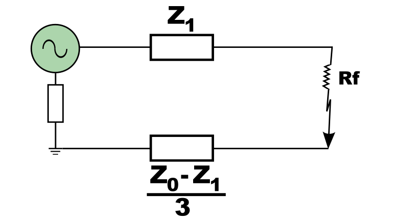
To understand the role of the K factor, let’s derive the impedance () seen by the relay for phase A during a single-phase-to-ground fault. Refer to the diagram provided above.
Current in Phase A (): From the fault loop in the diagram, the total impedance seen by phase A can be written as:
Here:
- = Voltage of phase A
- = Positive-sequence impedance
- = Zero-sequence impedance
- = Fault resistance
- = Zero-sequence component contribution to the fault loop.
Simplify the Denominator:
Combine the terms in the denominator to get:
Impedance Seen by the Relay ():
The impedance seen by the relay is defined as:
Substituting from the equation above:
Rearranging terms:
Incorporating the K Factor ():
The zero-sequence compensation factor is defined as:
Substituting with , the equation for becomes:
Key Observations
- The impedance seen by the relay is influenced directly by the K factor (), which adjusts the relay’s response to the zero-sequence impedance.
- accounts for the zero-sequence current's effect, which is essential for accurate fault location and impedance calculation.
- Fault resistance significantly impacts , necessitating careful estimation to avoid misoperation.
Clarification: While the classical formula for impedance is represented as , the derived equation accounts for zero-sequence current implicitly through the factor. The substitution simplifies the expression by expressing the zero-sequence contribution in terms of and .
Practical Fault Loop Analysis
Single-Phase-to-Ground Faults
For single-phase faults, the phase-to-ground loop is the most complex due to the integration of zero-sequence components. Miscalculation or incorrect settings for the K factor can lead to:
- Zone Overlap Issues: Triggering protection in unintended zones.
- Delayed Fault Clearance: Prolonged outages and potential system instability.
Validating Phase-to-Phase Loops
Although the focus is on single-phase faults, including phase-to-phase loop simulations is crucial for:
- Enhanced Phase-Selection Logic: Ensures non-faulted loops remain unaffected, avoiding misclassification.
- Improved System Dynamics Analysis: Observing impedance trajectories for better coordination.
Zero-Sequence Compensation in Action: Example
Consider a system with:
Calculate :
Determine :
Substitute the values:
This result confirms how influences the impedance calculation.
Conclusion
The K factor is critical in distance relay protection, ensuring accurate impedance calculations for single-phase-to-ground faults. By incorporating into the relay settings, engineers can improve fault detection accuracy and reduce misoperation risks.
Understanding the mathematical derivation and practical implementation of highlights its role in achieving reliable and stable protection systems.
The clarification regarding zero-sequence current was added to explicitly connect the derived equations to the classical representation and provide additional context for readers.