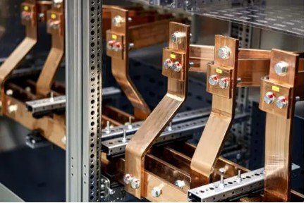
What is a Busbar?

A busbar is a high-conductivity metallic conductor used in substations to transmit electrical current and distribute power across various connected equipment like circuit breakers, transformers, and generators. It ensures continuity in power transmission and is crucial in the architecture of high-voltage networks.
Common Causes of Busbar Faults
Busbar faults in transmission and distribution networks can arise from various issues:
- Insulation breakdown due to aging, thermal stress, or contamination,
- Short circuits caused by external objects or internal failures,
- Mechanical failures from physical stress or improper installation.
These faults can lead to significant equipment damage, extended power outages, and severe safety hazards, underscoring the importance of robust protection schemes in the system.
Protecting Busbars with Relay Protection
Relay protection systems are critical in detecting and isolating busbar faults to minimize impact. Differential relays, the most common for busbar protection, monitor the current balance by comparing currents entering and leaving the busbar. A significant difference, indicating current loss due to a fault, causes the relay to initiate a trip signal. Differential relays provide quick, sensitive fault detection specifically tailored for busbars, improving system reliability and safety.
Types of Relays for Busbar Protection
- Differential Relay (87B): Uses Kirchhoff’s Current Law to compare the sum of currents flowing into and out of the busbar zone. A mismatch indicates a fault condition, and the relay triggers an immediate trip.
- Distance Relay (21): While not typically the primary choice for busbar protection, distance relays serve as backup protection. They measure impedance to detect fault distance, mainly effective in adjacent line protection scenarios.
High vs. Low Impedance Differential Relays
Differential relays for busbars can operate with either high or low impedance:
- High Impedance Differential Relays: Use a stabilizing resistor and offer reliable operation in systems with high fault currents. These are preferred when CT (current transformer) saturation could impact low-impedance settings.
- Low Impedance Differential Relays: Offer faster response times, with algorithms that calculate the restraint for stability under varying fault and load conditions. They can handle complex protection requirements and are more adaptable in modern substations.
Determining Relay Settings for Busbar Protection
Accurate relay settings are critical to ensure timely fault detection and appropriate selectivity. Key parameters include:
Pickup Current Setting: Determines the fault current threshold to trigger the relay. This setting is based on load current levels, fault current contributions, and CT ratios. Calculating the minimum fault current accurately helps avoid nuisance trips.
Time Delays: Coordinate with other protection devices, including nearby relays and circuit breakers, to ensure controlled and selective fault clearing. Time delays are essential for system stability, preventing simultaneous disconnections.
Example Calculation: Determining Pickup Current Setting
For a 220 kV busbar with a maximum fault current of 10 kA and a required safety margin, the pickup current setting can be calculated as follows:
Where is a safety factor (typically between 0.7 and 0.85 for reliability), and the CT Ratio converts fault current to a secondary current level.
Assuming:
- Fault Current: 10 kA,
- CT Ratio: 1000:1,
- Safety factor ,
The calculation becomes:
Setting the relay to 8 A ensures sensitivity to busbar faults without responding to normal load currents.
Standards and Best Practices
Following industry standards enhances the reliability and safety of busbar protection schemes:
- IEEE C37.234: Offers comprehensive guidelines for busbar protection systems, covering everything from relay selection to fault response timing.
- IEC 61850: Sets communication protocols for substation automation, enabling efficient data sharing and integration across protection devices for coordinated fault response.
- IEEE C37.112 and IEC 60255-151: Provide standard curves for overcurrent relays, assisting in time-current characteristic coordination essential in complex busbar zones.
Manufacturer Options for Busbar Protection Relays
Here’s a quick reference for busbar protection relay solutions from prominent manufacturers:
| Manufacturer | Low Impedance Protection | High Impedance Protection | URL |
|---|---|---|---|
| Siemens | SIPROTEC 7SS85 | SIPROTEC 7SS85 | Siemens Busbar Protection |
| Schweitzer Engineering Laboratories (SEL) | SEL-487B | SEL-787Z | SEL Busbar Protection |
| GE Grid Solutions | Multilin B30 | Multilin B30 | GE Multilin B30 |
| Hitachi Energy | REB500 | REB650 | Hitachi Energy Busbar Protection |
| ABB | REB500 | REB611 | ABB Busbar Protection |
| Toshiba | GRB200 | GRB100 | Toshiba Busbar Protection |
Conclusion
Ensuring effective busbar protection in high-voltage networks is essential for system stability and safety. Differential relays with precise settings, supported by international standards, enable robust protection against busbar faults. By adopting best practices and leveraging modern relay technology, power systems can maintain continuity and reduce risks associated with busbar faults.
Let us know in the comments if you’ve encountered busbar faults or have tips for relay settings!