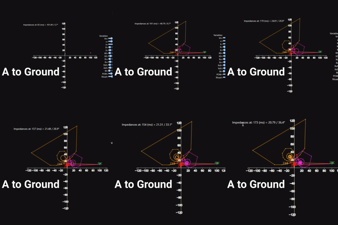
Understanding electrical faults is critical for designing and maintaining robust power systems. Among the most common fault types is the single line-to-ground fault, which occurs when one phase comes into contact with the ground.
What makes this fault scenario so fascinating is the dynamic way in which system impedances evolve during the fault, providing valuable insights into power system behavior under abnormal conditions.

This blog post dives into the visual representation of impedance changes during an A-to-ground fault, explores the engineering applications of this analysis, and outlines future simulation goals.
The Visual Insight
Traditional fault analysis often relies on numerical data or circuit diagrams. While these methods are effective, they lack the intuitive understanding that visual simulations can provide. The A-to-ground fault simulation brings these dynamics to life by showing how system impedances shift in real-time during a fault.
This simulation reveals how quickly the system reacts and adapts, which is critical for understanding system stability and fault-clearing mechanisms.
Why Impedance Matters
In power systems, impedance directly influences fault current magnitudes and voltage behavior. During an A-to-ground fault:
- Fault impedance changes dynamically: As the fault persists, impedances evolve due to factors such as system parameters, fault location, and transient response.
- Critical for protection design: Understanding these impedance shifts helps engineers fine-tune protection schemes, like distance relays (ANSI/IEEE device 21), which depend on accurate impedance measurements.
Mathematical Representation of Fault Impedance
For a single A-to-ground fault, the impedance seen by the system can be derived from symmetrical components:
Where:
- is the positive-sequence impedance,
- is the negative-sequence impedance,
- is the zero-sequence impedance.
The fault current, , is given by:
Here, is the pre-fault voltage at the fault location, and represents the impedance of the fault path (often dominated by the grounding system and fault resistance).
By visualizing these changes, we can better analyze fault conditions and design systems that quickly and effectively isolate faults, preventing cascading failures.
Future Steps
While this simulation focuses on the single line-to-ground fault, this is just the beginning. Upcoming simulations will include:
- Phase-to-phase fault simulations: Visualizing how impedances evolve when a fault occurs between two phases. The fault impedance for such cases is typically derived as:
Zf_{LL}} = Z_1 + Z_22. Phase-to-phase-to-ground fault simulations: Adding the complexity of a ground path to phase-to-phase faults. The impedance calculation becomes more intricate due to the contribution of the ground path impedance :
Zf_{LLG}} = Z_1 + Z_2 + \frac{Z_0}{3}These simulations will provide a comprehensive picture of fault behavior in power systems, supporting engineers in their analysis and design efforts.
Engineering Applications
Beyond their visual appeal, simulations like this are invaluable in real-world engineering contexts. For instance:
Protection schemes: Engineers can design more effective relays by understanding how impedance evolves under fault conditions. For example:
- Distance relays (ANSI/IEEE device 21) use impedance zones to detect and clear faults based on their location relative to predefined thresholds.
- Directional relays (ANSI/IEEE device 67) can identify fault directionality by analyzing phase shifts.
Fault location: Impedance evolution can be used in algorithms for locating faults on transmission lines, employing methods like impedance-based fault location or traveling wave analysis.
Training and education: Visualizing fault dynamics helps students and professionals grasp concepts that might otherwise remain abstract, particularly for transient analysis and relay coordination.
Conclusion
Simulations of electrical faults, like this A-to-ground fault visualization, bridge the gap between theoretical understanding and practical application. By bringing complex concepts to life, they make it easier for engineers, students, and enthusiasts to explore the intricacies of power system behavior.
Stay tuned for updates as I work on completing the next stages of this project, including phase-to-phase and phase-to-phase-to-ground fault simulations!